| Brand: | JK Impex |
| Model: | GDS07 |
| Country: | India |
| Signal Output : | PWM UART |
| Detection Principle: | Infrared light scattering |
| Detection Range: | 0.3~10μm |
| Working Current: | <20mA |
| Standby Current: | <0.1mA |
| Storge Conditions: | -20~80℃ , 0~95% RH |
Description of S7-L Smart Dust
Based on the optical correlation theory, the S7-L Smart Dust Sensor can detect the number of particles and concentration data precisely in the handles and extension tubes of vacuum cleaners as well as in the ventilation ducts of sweeping robots, kitchen ventilators, particle detectors, etc.
Application Benefits of S7-L Smart Dust Sensor for Vacuum Cleaners and Sweeping Robots:
The cleaning effect of the device and the cleanliness of the floors, carpets, bed sheets can be visually presented to the users through the sensor output data and the color display of LED;
The device controls the rotation speed of the motor in an intelligent way in accordance with the sensor data, in order to remain mute, conserve energy and power as well as prolong the life of the motor;
Product Features of S7-L Smart Dust Sensor:
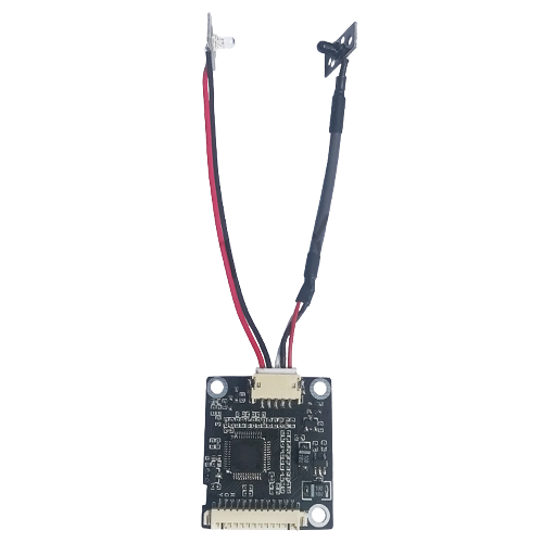
The product takes use of the correlated and separated structure in emission and reception, with a small size, and is quite easy to be installed and used in various complicated conditions;
The accuracy of motion measurement is high, and the minimum detected particle size is 10um at the wind speed of 12m/s;
The measurement sensitivity is high, with the response time less than 0.6s;Wide measurement range: two measurement options of 0-999 and 0--9999;
Low power consumption: operating current less than 30mA, and dormant current less than 0.5mA.
The output interface contains the LED drive level with the particle concentration of seven colors composed of 3PIN.
The data output interface of particle concentration: PWM and UART can provide accurate dust concentration data for vacuum cleaners, sweeping robots and other devices in real time.
Application Fields
◆ Vacuum cleaners
◆ Sweeping robots
◆ kitchen ventilators
◆ Intelligent detectors
1.4 Basic characteristics
<Notes>
The product is only applicable to the above-mentioned application fields in principle. And when used for other purposes, it needs to be verified by users.
The product should be placed away from high frequency and high voltage to avoid the interference caused by high frequency and high voltage.
Irregular vibration may make the measurement error of the product increase.l
External light may make the measurement error of the product increase. Thus, when installing the device, users should avoid external light.
Notes of circuit design:
1. 5.0V needs to be as the high level for the data communication and control pins of the S7-L output interface.
2. The pull-up resistor inside SET and RESET should be suspended, if not used.
3. PIN7 is used for internal debugging of the program, which should be suspended in the application circuit.
4 The R\G\Y drive output should be connected to the peripheral switching circuit. For instance, the circuit in Figure 1 is for reference only.
Data Transfer
UART output
The sensor adopts standard full-duplex UART serial port communication, with the baud rate of 9600bps. What should only be received in the application process is the dust concentration data, and in the default state, the sensor remains working. The dust concentration value can be gotten after the serial port data is decoded, with the unit of mg/m². The communication format and data decoding of serial ports in details can be found in Appendix 1.
PWM output
The PWM signal is outputted through the PWM port, and the PWM period is 1S. Besides, the dust concentration value is calculated based on the low level width.
Relationship between low pulse time and dust concentration: 1ms = 1 mg/m²
For instance, when the width of low level is 100ms, the dust concentration is 100 mg/m². And the output range of PWM concentration is from 5 mg/ m² to 800 mg/m².
Installation notes:
The transmitting tube is connected with the sensor body by wires;
The transmitting tube should remain 180°against the receiving tube;
The distance between the transmitting tube and the receiving tube should keep less than or equal to 60mm;